Notes on Surveyor Coded Metadata Fields
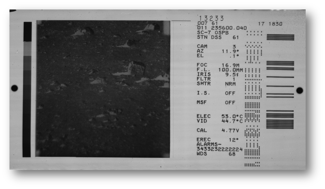
Image frames from the Surveyor missions contain both “human readable” and “machine readable” information to identify the various parameters important to the images.
The “human readable” information consists of text and numeric characters printed on the film frame with dot matrix characters formed within a 6x6 dot space similar to dot matrix printers. There is only upper case text and numerals used for field labels and field data. Where necessary symbols are created by using a lower case “f” to represent “ƒ stop” and a small circle of dots to represent “( ° ) “degrees”. The text values are obtained from lookup tables referenced by decoding the serial data fields contained within the dot pattern.
The “machine readable” information is written in two data fields one field is represented by a pattern of dots, and the other is coded into bars appearing at the right side of the film frame. The field of dots contains the technical parameters of the image frame; such as azimuth, elevation, focal length, focus and exposure parameters.
The dot pattern is a series of binary number fields consisting of a 10-bit word with 1 parity bit, making a total of 11 possible ones or zero’s. The fields are coded using odd parity, meaning if there are an even number of dots in the coded word then the 11th bit is shown creating an odd number of bits in the field. There are a total of 16 fields (binary words) arranged vertically from top to bottom for each image.
The groups of 16 fields are repeated multiple times, but the series starts at random positions with in the dot field; and will wrap from the bottom of one column to the top of the next. The column wrapping occurs after 80 (mission I & III) or 88 (missions V, VI, VII) dot positions. Each group of 16 begins with a “barker” word consisting of [00011101101] this field can also be referred to as the “start of message – end of message” flag, “header field” or “ID field”. There are 12 columns on the mission I and III films, and 11 columns on mission V, VI, VII films. The first and last columns on most film frames are random data bits and do not contain decodable information, it is suspected this is due to noise being generated in the Surveyor analog to digital converter from the video sync pulses mixing with the analog voltage data at the beginning and end of the data encoding.[1]
The pattern of bars represents (encodes) the identifying information for the image; mission (A-G) for Surveyor 1 – 7, the Deep Space System (DSS) receiving the image, the numerical day of the year and the GMT time of the exposure in HHMMSS.sss format. The bar to bar spacing exactly aligns with the vertical spacing of the dot field bit timing. The beginning of the bar field aligns with the rows of the dot field; this provides a convenient positioning to determine the one and zero bit position information.
There appears to be two sections to the bar data; an upper section that remains consistent for a series of images, changing when the mission day or receiving site changes. The start of the bar field begins in linealigns with the first horizontal row of dots.; the first data bit usually appears beginning on the fourth bit position. The first 36 positions contain the unique identifiers for the image frame. The data is encoded using Binary Coded Decimal (BCD) from an octal number. The first field, bits 1-6 is the data source, this is the origin of the data used to create the image on the cathode ray tube (CRT or kinescope), and recorded by the film camera. The next field on bits 11-22 is the mission as a 3 place BCD, again from an octal number., since Missions were I – VII, and Missions II and IV were unsuccessful and there are no image frames; the coded numbering would beI is slightly different, on bits 7-13 the original roll number is coded as a seven bit binary number: seems to follow the receiving station although the bits don’t appear to directly translate to a decimal number that correlates to the DSS designation, (11, 1011)(42, 101010) or (61, 11101).
The center of the upper section starting on row 19 encodes the mission as a 4 bit binary number, spaces indicate 0, bars indicate binary 1;
Mission 1 – 0000nnnnnn 0000 00001 (001)
Mission 3 – 0000 0000 00011 (003)
Mission 5 – 0000 0000 00101 (005)
Mission 6 – 0000 0000 00110 (006)
Mission 7 – 0000 0000 00111 (007)
Next is the Receiving site or DSS, again the numbers are in octal, then BCD coded, each digit occupies 4 bits. DSS designations, (11, 0001 0001)(42, 0100 0010) or (61, 0110 0001).
The lower part of the section encodes the GMT time that each image was taken. On initial examination the sequence appeared to follow the conventional USNO convention for BCD time encoding, with HH:MM:SS fields separated by a binary 0 (open space). “A binary-coded decimal time code began testing in 1960, and became permanent in 1961. This "NASA time code" was modulated onto a 1000 Hz audio tone at 100 Hz, sounding somewhat like a monotonous repeated "baaga-bong". The code was also described as sounding like a "buzz-saw".[1]
The time coding on the films is not actually BCD, but serial data fields laid out in the convention of the NASA Parallel Grouped Binary Time Code PB-1[2]; representing [milliseconds] [day of year] [hours] [minutes] [seconds]. The time bit fields start at row 37 and continue for the next 36 spaces. There is no blank spaces or bars separating the fields.
- Milliseconds (.000 - .999) 10 bits 0000000000 – 1111100111
- Day of year (1-366} 9 bits 000000001 – 101101110
- Hour (0 – 23) 5 bits 00000 – 10111
- Minute (0-59) 6 bits 000000 – 111011
- Second (0-59) 6 bits 000000 – 111011
- From row 74 to 88 (row 80 for Surveyor I & III) there appears to be no data or markings
There is additional clarification and research for the upper half of the bar code field, including identifying the coding for images made from tape sources and relayed receiving sites.
Notes on Surveyor BCD Field from SMPTE and IEEE Journal Articles
Read back (analog position voltages)
- The DC-DC converter input is from the Surveyor +29 volt regulated power supply. The +29 volt supply is regulated to ± 2%. The DC-DC converter supplies the +4.85 voltage.
- The reference voltage is not subsequently regulated so it remains a ± 2% tolerance, thus can vary from 4.735 volt to 4.947 volt (4.73v to 4.95V)
- Position potentiometers are supplied from the +4.85 v output of the DC-DC converter.
- Wire-wound potentiometers as used in Surveyor are typically 5% tolerance.
- Accounting for the supply and potentiometer tolerances, reference voltage reported as cal voltage could vary from 4.49v to 4.95v.
- Assuming a 10 bit resolution, with 5.0v =1023 and 0.0v = 0 then the number binary works.
- This equates to a resolution of 4.883 mV. So 4.49v = 919d = 11,1001,011b and 4.95v = 1013d = 11,1111,0101b.
Binary data
- While called “BCD” each data field is a simple binary coding of 11 bits, 10 data and 1 parity.
- Fields are coded using “ODD” parity, if the count of “1” bits is even the parity bit is set making the count of “1” bits odd.
Regarding the steps of azimuth and elevation:
- Elevation is steps of 2.48° ± 0.1°
- Azimuth steps are 3.0° ± 0.1°
Variable steps
- Iris has 11 referenced positions from ¦4 (wide open) to ¦22 (fully stopped down)
- Positions are approximate, resolve to 2 decimal (0.02 – 0.95) and select closest ¦-#
- Focus (FOC) of the lens ranges from 4ft to ¥. The calibration table defines values as:
- 0.036 (BCD 35) = 4 ft. or closest focus
- 0.975 ((BCD943) = 653 ft.; this would be the ¥ position of the lens
- Closest value to corrected BCD is the approximate focal distance.
- Lens focus distance was referenced in earth atmosphere; image distance resolving by focus may not be accurate.
Other fields
- Iris Servo (I.S.) is on or off, a blank field (00000000001) is “OFF” any thing else is “ON”
- Camera (CAM) is always 3, Camera 2 was down looking on Surveyor I, Never a Cam.1
- Focal Length (F.L.) any value above 100 (0001100100) is telephoto, »100.7MM otherwise is »25MM
- Multistep Focus (MSF) high number is ON low number is OFF
- Filter Wheel only has 4 steps, with limit stops and can’t continually revolve.
- 0 (fully CCW) or 0.7 (fully CW) is the clear or ND filter
- 0.5 is position 3
- 0.3 is position 2
- 0.1 is position 1
References:
- H. Kruger and J. Williams, “Surveyor Television Power Conditioning, Jour. SMPTE, 77: 337-341, Apr 1968
- R. Rechter “Signal Processing and Transmission for the Surveyor Television System”, jour. SMPTE 77: 341-350, Apr.1968
- D. Montgomery and F. Wolf, “The Surveyor lunar landing television system”, IEEE Spectrum: 54-61, Aug. 1966
- D. Heckel, “Unit and System Design of a Lunar Operating TV Camera”, Jour. SMPTE, 76: 773-779, Aug. 1967
[1] Rechter, R. J. (1968). Signal Processing and Transmission for the Surveyor Television System. Journal of the SMPTE, 77(4), 341-350.
[2] Wikipedia: WWV (radio station)
[3] A.R. Chi, , A Grouped Binary Time Code for Telemetry and Space Applications NASA –TM-8086 Dec. 1979